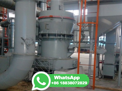
coal gasification process flow diagram

Fuels | Free FullText | Process Analysis and Design ... MDPI

Fuels | Free FullText | Process Analysis and Design ... MDPI

The block flow diagram depicts the integration of the selected process units for the synthetic methanol plant . In particular, the proposed value chain begins with the gasification unit that converts the solid feedstock consisting of predried lignite coal (LEG) and solid recovered fuel (SRF) into a hot raw syngas by means of an HTW gasifier.

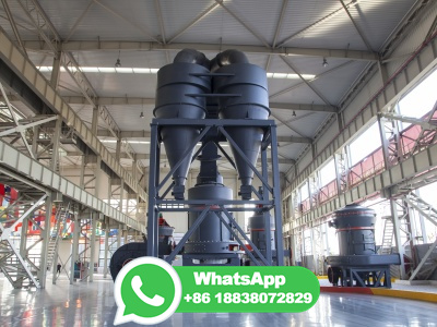
PDF Conceptual Design Development of CoaltoMethanol Process with Carbon ...

PDF Conceptual Design Development of CoaltoMethanol Process with Carbon ...

Energies 2020, 13, 6421 3 of 21 with the methanol synthesis process. VanDal et al. [18] designed and simulated the conversion of CO2 and H2 to methanol using Aspen Plus. They proposed to capture CO2 from a coal fired power plant and produce H2 from the water electrolysis. Their results showed that ton of CO2 can be abated per ton of methanol production.

Integrated Gasification Combined Cycle an overview ScienceDirect

Integrated Gasification Combined Cycle an overview ScienceDirect

The coalbased gasification concepts are slightly more efficient than the combined coal biomass gasification concepts by about to net energy efficiency points. Also, calcium looping option is more energy efficient than reactive gasliquid absorption. ... Simplified process flow diagram for hydrogen or energy production from gasified ...

Modelling approaches for biomass gasifiers: A ... ScienceDirect

Modelling approaches for biomass gasifiers: A ... ScienceDirect

Flow diagram of technologies and process for gasification. The biomass gasification process includes four major steps which are: Drying, Pyrolysis, Combustion Reduction/gasification. ... Entrained flow gasifiers with capacities higher than 100 MWe are used in roughly 10% of the world's IGCC systems for coal gasification (Gopalakrishnan, 2013c ...

 GasificationBased Hydrogen Production with Carbon Capture

GasificationBased Hydrogen Production with Carbon Capture

Figure 1: Block flow diagram, hydrogen production coal gasification plant with CO2 capture 1 Figure 2 shows a variation of the gasificationbased hydrogen production plant with 90% CO 2 capture from Figure 1, but in this case consisting of a coal and woody biomass cogasification configuration.

Process Analysis of Chemical Looping Systems for Dimethyl Ether ...

Process Analysis of Chemical Looping Systems for Dimethyl Ether ...

Process flow diagram of conventional coal gasificationDME system (Goellner et al. 2014; Tan et al. 2015) Full size image In the conventional gasification process, after drying, coal is fed into the coal gasifier along with steam and O 2 obtained from ASU to produce raw syngas.

 Typical IGCC Configuration |

Typical IGCC Configuration |

Figure 2 : IGCC Block Flow Diagram. A more detailed process description of each of the processing units within an IGCC complex is presented in the discussion on IGCC process system sections. Effect of CO 2 Capture The flow scheme of Figure 2 represents a typical process arrangement of a nearterm commercial IGCC design without CO 2 capture.

FACT SHEET SERIES H1 ffactsacts hydrogen

FACT SHEET SERIES H1 ffactsacts hydrogen

sequestration technologies (see The Gasifi cation Process diagram below and the text box on page 2). The Process Step 1: Gasifi cation Gasifi cation turns coal into a very hot (up to 1800°C) synthesis gas, or syngas, which is composed of carbon monoxide, hydrogen and carbon dioxide, as well as small amounts of other gases and particles.

Coal Gasification: At the Crossroads. Economic Outlook

Coal Gasification: At the Crossroads. Economic Outlook

The coal gasification plant capacity is 1800 t/day of coal. A process flow diagram of syngas production from coal is presented in Fig. 1. Fig. 1. ... considers two technologies of oxygen coal gasification: 1. The GSPprocess: hightemperature entrained flow gasification of pulverized coal (first option); industrial applications are available; ...

PDF Syngas Production from Coal

PDF Syngas Production from Coal

counterflow to coal. An important feature of the Lurgi dry bottom gasifier is the low consumption of oxygen and the high steam demand. Movingbed gasifiers need ... KoppersTotzek, Shell Coal Gasification Process (SCGP), Prenflo, Siemens, GE Energy,EGas, Mitsubishi Heavy Industries (MHI), Eagle molten slag bath. The much lower steam and somewhat

PDF February 2017 ihs SP Global

PDF February 2017 ihs SP Global

Shell Coal Gasification Process (SCGP) 48 Appendix A—Cited references 53 Appendix B—Process flow diagrams 55. Tables . Table 1 GE quench gasification —Total fixed cost 8 Table 2 GE quench using bituminous coal—Production costs 9 Table 3 GE quench using subbituminous coal—Production costs 10 Table 4 Shell gasification using bituminous ...

Hydrogen Production: Biomass Gasification Department of Energy

Hydrogen Production: Biomass Gasification Department of Energy

Replacing the cryogenic process currently used to separate oxygen from air when oxygen is used in the gasifier with new membrane technology. Developing new membrane technologies to better separate and purify hydrogen from the gas stream produced (similar to coal gasification). Intensifying the process (combining steps into fewer operations).

How to Use Process Flow Diagrams for Coal Gasification Training LinkedIn

How to Use Process Flow Diagrams for Coal Gasification Training LinkedIn

To ensure safe, efficient, and sustainable operations, coal gasification engineers and operators need to have a solid understanding of the process flow diagrams (PFDs) that represent the...

Conceptual Design Development of CoaltoMethanol Process with Carbon ...

Conceptual Design Development of CoaltoMethanol Process with Carbon ...

Figure 1 shows the simple process flow diagram for the methanol production from the reforming of ... Depending on the coal composition and gasifier technology, the typical syngas ratio (H 2:CO) produced from the coal gasification process is in the range of [31,32] which does not achieve the required stoichiometric ratio as shown in ...

 Gasification Introduction |

Gasification Introduction |

Library Gasification Introduction Gasification is a technological process that can convert any carbonaceous (carbonbased) raw material such as coal into fuel gas, also known as synthesis gas (syngas for short).

Environmental impact and technoeconomic analysis of the coal ...

Environmental impact and technoeconomic analysis of the coal ...

The coal gasification process is modelled by Aspen Plus (V ). The process flow diagram of the coal gasification process is shown in Fig. handling capacity of coal is set to be 300 t/h, referring to the coaltoolefins process in Baotou, China (Zhang et al., 2013).According to the previous work (Yang et al., 2012), the gasification temperature and pressure are fixed at 1723 K and ...

 Methanol Plant Process Configurations |

Methanol Plant Process Configurations |

Library. Methanol Plant Process Configurations. Figure 1 shows a simplified block flow diagram (BFD) of a methanol (MeOH) plant based on coal feedstock. Syngas from the gasifier is cooled by generating high pressure (HP) steam in the high temperature (HT) gas cooling system before being water quenched and scrubbed to remove fine ...

Coal gasification Wikipedia

Coal gasification Wikipedia

In industrial chemistry, coal gasification is the process of producing syngas —a mixture consisting primarily of carbon monoxide (CO), hydrogen ( H2 ), carbon dioxide ( CO2 ), methane ( CH4 ), and water vapour ( H2O )—from coal and water, air and/or oxygen. Historically, coal was gasified to produce coal gas, also known as "town gas".

Flowchart of gasification model. | Download Scientific Diagram

Flowchart of gasification model. | Download Scientific Diagram

The flowchart of the computations in the model is presented in Fig. 1. The input parameters for the model are coalfeed rate, coal properties, gasification temperature and pressure,...

Process flow diagram of coal gasification ResearchGate

Process flow diagram of coal gasification ResearchGate

A schematic process diagram of coal gasification is shown in Figure 1. Multispot and multidepth sampling methods were applied to obtain a laboratory sample, and the samples suitable for the...

Energies | Free FullText | Numerical Analysis for Coal Gasification ...

Energies | Free FullText | Numerical Analysis for Coal Gasification ...

The optimization of multiple factors for gasification performance using a 3D CFD model with advanced submodels for singlestage drop tube coal gasification was compared with experimental results. A singlestage downdrop gasifier with multiple coal injectors and a single oxygen injector at the top of the gasifier was investigated at different temperatures and O2/coal ratios. A finite rate ...

PDF Gasification System: Process Flow Eastern Illinois University

PDF Gasification System: Process Flow Eastern Illinois University

Description The Gasifier is a downdraft biomass gasifier that allows the user to create syngas that can be used to run an engine or generate electricity. Figure 1 shows a profile diagram that identifies the material and gas flow in the gasification system. Figure 1: Profile Picture of the Gasification System Process Flow

PDF Introduction to Ammonia Production AIChE

PDF Introduction to Ammonia Production AIChE

cant quantities are produced by coal gasification; most of the gasification plants are located in China. Modern production processes The tremendous increase in ammonia demand from 1950 to 1980 necessitated larger, moreenergyefficient plants. Those decades also saw a change in design philosophy. Until

PDF Technical Manual for the SAM Biomass Power Generation Model

PDF Technical Manual for the SAM Biomass Power Generation Model

different types of solid fuels, including biomass and coal. ... For example, biomass gasification ... Figure 1. Biomass power process flow diagram . 3 Biomassfired power plants employ the same basic unit operations as a coalfired power plant, making cofired power plants that can run on either feedstock (or both in parallel) ...

4 Flow diagram of a typical coal gasification plant.

4 Flow diagram of a typical coal gasification plant.

... The LCOH estimates for biomass gasification with carbon capture and storage available in the literature are scarce; only two LCOH values were found [ /kgH 2 and /kgH 2 ] [5, 58]. The...